Chat with us, powered by LiveChat

Tube Fitting Installation Guide

Preperation

To begin your tube fitting installation, first prepare the tubing to be installed. Ensure the tubing is cut straight and plumb, perpendicular to the length of the tube. Be sure to remove all burr or debris from the end of the tubing that may be left over from cutting. Finally, inspect the tubing to ensure there is no damage or imperfections that may constitute a weak point, especially in the area that will engage with the ferrules.

Note for Gas Systems

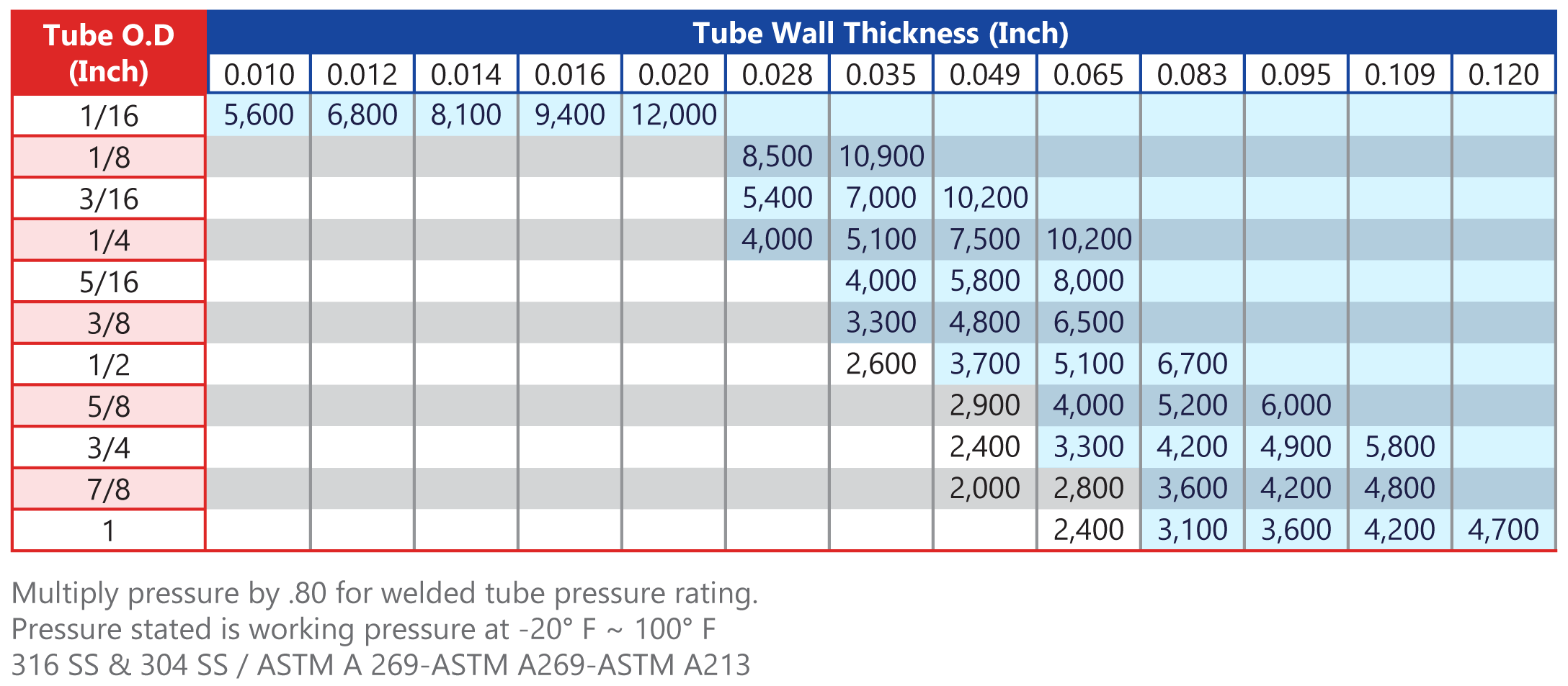
Gas systems require a high-quality seal. Thinner wall tubing deforms more easily, leading to a higher risk for possible leaks through surface imperfections in the tubing. Using thicker wall tubing for gas systems requires more pressure on the ferrules, causing them to coin out these imperfections, improving the seal. It is for this reason that tubing for gas systems should be selected from the shaded zone on the pressure chart.

(Tubing Chart goes here)

Industry Standard Installation Instructions (1" and Smaller)

This installation guide section is for standard twin-ferrule instrumentation tube fittings and should apply to most fittings produced by high-quality fitting brands.

Required Tools

  • Fittings and Tubing of Desired Size
  • Wrenches Appropriate for the Selected Fittings
  • Permanent Marker
  • Gap Gauge Tool (Most manufacturers offer a gauge for their specific fittings.)

Installation

  1. Insert the tube into the fitting until it rests on the stop shoulder inside the fitting. Ensure that the tubing easily slides into the fitting and does not have to be forced.
  2. Tighten the compression nut by hand until it cannot be tightened further.
  3. Using the permanent marker, mark the nut and the fitting body at the 6 O'clock position. This will make it easier to keep track of how many turns the nut has made in the next step.
  4. Using one wrench to stabilize the fitting body, use a second wrench to tighten the compression nut 1-1/4 turns from the hand-tight position (tighten only 3/4 turns for fittings 3/16" and smaller).
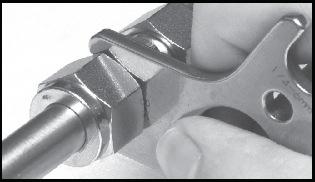
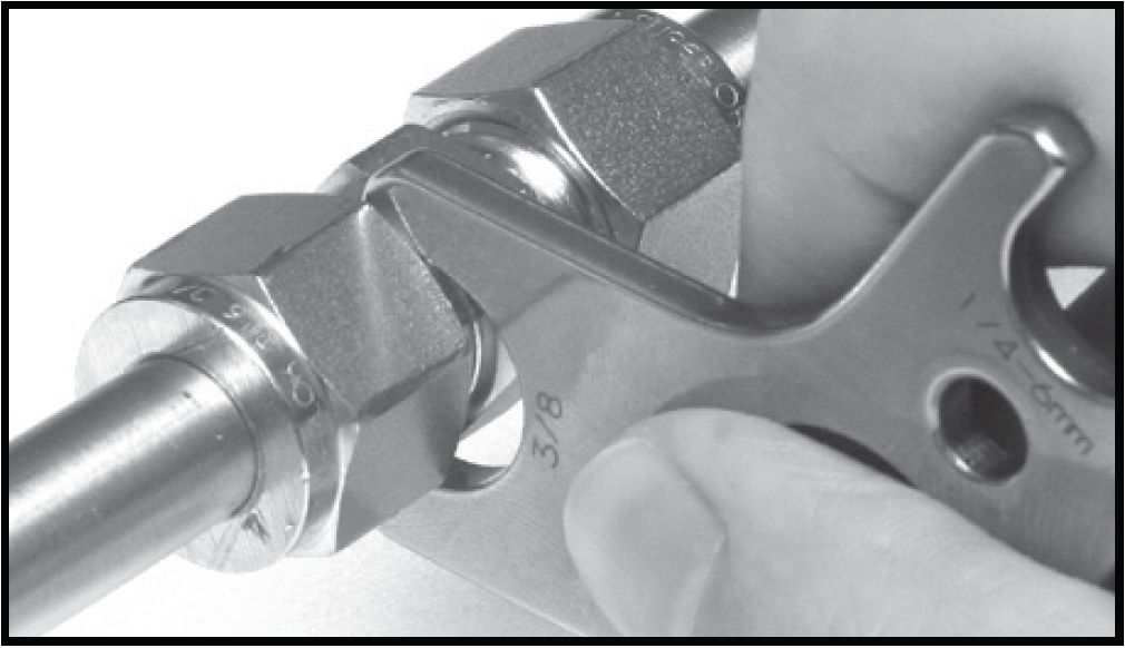
  5. Inspect the gap between the compression nut and the fitting body with a gap gauge. If the gauge slips easily into the gap, tighten the fitting slightly more until the gauge no longer fits.

Gap Gauge Fits into Gap - Additional Tightening Needed
Correctly Installed - Gap Gauge Does Not Fit

Superlok i-Fitting Installation Instructions (1/4" - 1")

This installation guide section is for Superlok i-Fittings with built-in gap gauge technology.

Required Tools

  • i-Fittings and Tubing of Desired Size
  • Wrenches Appropriate for the Selected Fittings

Installation

  1. Insert the tube into the fitting until it rests on the stop shoulder inside the fitting. Ensure that the tubing easily slides into the fitting and does not have to be forced.
  2. Tighten the compression nut by hand until it cannot be tightened further.
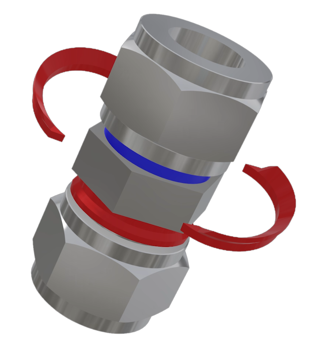
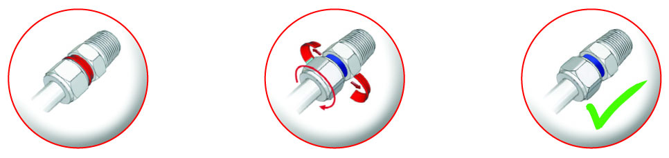
  3. Using one wrench to stabilize the fitting body, use a second wrench to tighten the compression nut until the red indicator band pops away from the fitting (1-1/4 Turns from hand tight).

Note* There is no need to check the gap with a secondary tool. The red indicator ring is a built-in gap gauge that is more acurate than the supplied gauges for standard tube fittings.

Helpful Links

Connect with Our Team

Our team is eager to help answer any questions you may have. Reach out by providing your information below and we'll gladly connect.

Thank you! Your submission has been received!
Oops! Something went wrong while submitting the form.

Contact Info

Location

14808 Metro Plaza Blvd.
Edmond, OK 73013

Find Us
E-mail Address

sales@mako-products.net

E-mail Us
Phone

Local: 405-509-2665
Toll Free: 1-844-200-MAKO (6256)

844-200-6256